GPIO:General Purpose Input Output,通用输入输出。可以理解为树莓派电路板插针上的pin脚。下文统一用pin脚指代。
一、pin脚映射
树莓派有三种pin脚映射:BOARD、BCM、Pi4J/WiringPi。
1、BOARD/BCM
BOARD、BCM:这两种映射方式可以在pinout网站查看,或者在终端输入pinout查看。
BOARD:下图中从左到右依次为1-39pin和2-40pin;
BCM:下图中的14、15、18、23、24、25、8、7、1、12、16、20、21等pin。
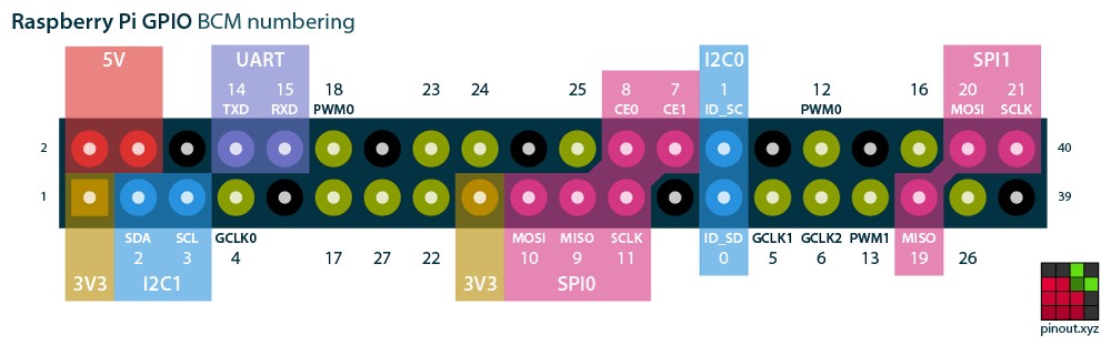
玩过单片机的同学应该知道,很多单片机带有丰富的片内外设。譬如MSP430单片机,芯片里不仅有MCU,还有定时器、看门狗、UART、SPI、I2C等常见模块。
树莓派的SoC也是一样,集成了很多模块,因此它的pin脚也具备复用功能。如:UART、I2C、SPI。不开启复用功能时为通用pin脚,具备输入输出功能;开启复用功能后,就具备了相应模块的功能。譬如BCM模式下的14、15脚(上图紫色),开启复用功能后就可以与串口进行通信。
2、Pi4J/WiringPi
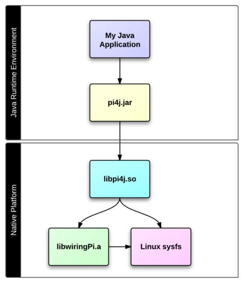
WiringPi是用c写的树莓派GPIO库。Pi4J是树莓派GPIO的Java库,依赖于WiringPi。
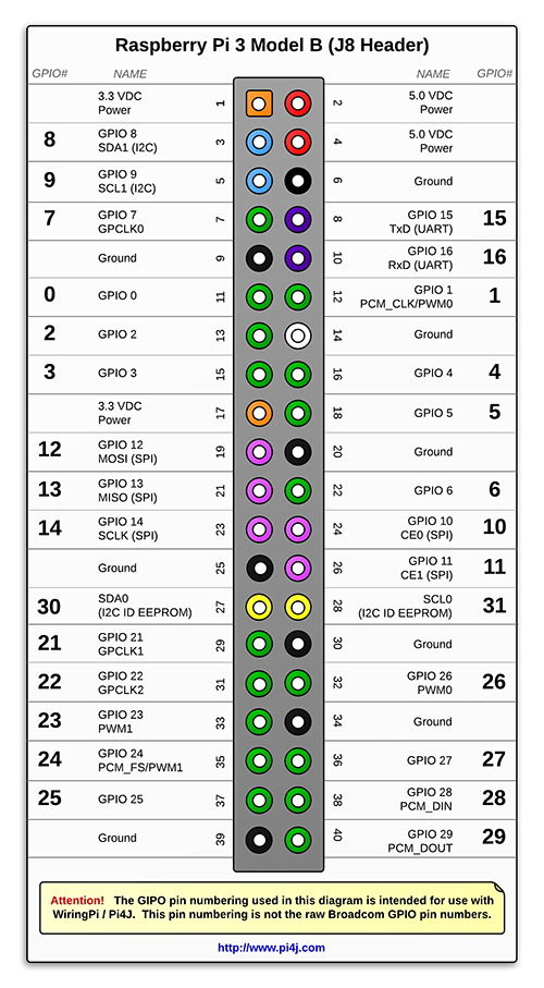
Pi4J/WiringPi模式下的pin脚映射如下图。
二、基本使用
1、Python
安装:pip3 install RPi.GPIO
教程:raspberry-gpio-python,从基本使用到输入/输出再到pwm,样例写的很清晰了,直接在板子上试就可以了。
基本套路就是:
1
2
3
4
5
6
7
8
9
10
11
12
# 1、引入包
import RPi.GPIO as GPIO
# 2、设定模式BOARD、BCM,Python只有这两种
GPIO.setmode(GPIO.BOARD)
# 3、设定输入、输出
GPIO.setup(12, GPIO.OUT)
# 4、开始输入或者输出
GPIO.input(12)
GPIO.output(12, GPIO.LOW)
# 5、关闭资源
GPIO.cleanup(12)
GPIO.cleanup()
2、Java
安装:通过maven引入或者直接下载jar包作为lib,Pi4J :: Java Library (Core) » 1.2
教程:官网的examples很详尽了。
下面是个pin脚的例子,控制GPIO_01(Python下的BOARD.12)高电平5s再低电平5s两个来回,最后输入个1秒的高电平脉冲。如果接了led,会看到相应的led亮灭和脉冲。(ps:接led时记得接限流电阻)
1
2
3
4
5
6
7
8
9
10
11
12
13
14
15
16
17
18
19
20
21
22
23
24
25
26
27
28
29
30
31
32
33
34
35
36
37
38
39
40
41
42
43
44
45
46
47
48
49
50
51
52
53
54
55
56
57
58
59
60
import com.pi4j.io.gpio.GpioController;
import com.pi4j.io.gpio.GpioFactory;
import com.pi4j.io.gpio.GpioPinDigitalOutput;
import com.pi4j.io.gpio.PinState;
import com.pi4j.io.gpio.RaspiPin;

/**
 * This example code demonstrates how to perform simple state
 * control of a GPIO pin on the Raspberry Pi.
 *
 * @author Robert Savage
 */
public class ControlGpioExample {

    public static void main(String[] args) throws InterruptedException {

        System.out.println("<--Pi4J--> GPIO Control Example ... started.");

        // create gpio controller
        final GpioController gpio = GpioFactory.getInstance();

        // provision gpio pin #01 as an output pin and turn on
        final GpioPinDigitalOutput pin = gpio.provisionDigitalOutputPin(RaspiPin.GPIO_01, "MyLED", PinState.HIGH);

        // set shutdown state for this pin
        pin.setShutdownOptions(true, PinState.LOW);

        System.out.println("--> GPIO state should be: ON");

        Thread.sleep(5000);

        // turn off gpio pin #01
        pin.low();
        System.out.println("--> GPIO state should be: OFF");

        Thread.sleep(5000);

        // toggle the current state of gpio pin #01 (should turn on)
        pin.toggle();
        System.out.println("--> GPIO state should be: ON");

        Thread.sleep(5000);

        // toggle the current state of gpio pin #01  (should turn off)
        pin.toggle();
        System.out.println("--> GPIO state should be: OFF");

        Thread.sleep(5000);

        // turn on gpio pin #01 for 1 second and then off
        System.out.println("--> GPIO state should be: ON for only 1 second");
        pin.pulse(1000, true); // set second argument to 'true' use a blocking call

        // stop all GPIO activity/threads by shutting down the GPIO controller
        // (this method will forcefully shutdown all GPIO monitoring threads and scheduled tasks)
        gpio.shutdown();

        System.out.println("Exiting ControlGpioExample");
    }
}